
Page 30 - MSc_thesis_R A Kil
P. 30
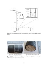
Air inlet                                    Tube wall     Water
Three-way valve                                      Rubber seal

                Plug                                 Sample
                                                     Spacer
                 h(t)
                                                                      Water tank bottom

                          Vacuum pump

                       L                                           H

Sample

Figure 3.3 – Schematic overview of the experimental set-up used for the permeability measure-
ments.

(a) A prepared sample with its seal. Flow of         (b) Cross-sectional view of a calcarenite sam-
water would in this case be from left to right.      ple.

Figure 3.4 – Examples of a calcarenite plug prepared for permeability tests, including the
rubber bicycle inner tyre that serves as a seal.

                                                 13