
Page 5 - EAI-4_2015_48-59
P. 5
describe the seasonal variability of the beach morphology Survey vessel and personnel for marine operations were
as completely as possible, compatibly with the timetable provided by the Marine Reserve Management Authority
of the project and suitable sea and weather conditions. (Area Marina Protetta Isole Egadi). The transducer was
Survey equipment and instrumentation are listed below: mounted at the port side of the vessel, using a flange
• Multibeam echo sounder with sidescan sonar Odom pole and an ad-hoc-designed steel framework.
As regards the navigation project, survey lines normal to the
Echoscan (30 beams, acoustic frequency 200 kHz, shoreline were adopted, oriented to North for Cala Azzurra
swath angle 90°); and 45°N for Lido Burrone, respectively. Line spacing was
• Marine Differential GPS Trimble SPS461, dual defined,considering the multibeam swath angle,in order to
antenna, for position and heading measure; obtain, at nominal depth of 10 m, a 100% bottom coverage
• Trimble HydroPro software for survey planning and with 50% overlap between parallel consecutive swath lines.
navigation; Overall, 30 transects were adopted for both sites, with 10 m
• Communication Technology GeoPro/SwanPro line spacing.The orientation and spacing of survey lines is
software for multibeam and sidescan sonar data the result of an optimal compromise between swath angle
acquisition; and resolution of the instrument, maneuverability of vessel
• Triton BathyPro, Triton ISIS Sonar and Golden and safety of navigation, and allowed to maximize the
Software Surfer software for data processing and surveyed area, also considering the bottom morphology
presentation. and the presence of rocks and other obstacles in the
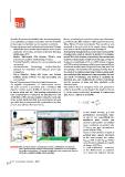
Figure 3 shows some of the above listed resources. nearshore zone.
As regards compensation of measurement errors, The offshore limit of navigation lines was planned in
the echo sounder is provided with a Teledyne TSS order to extend the survey beyond the depth of closure
dynamic motion sensor (DMS) for random errors due dc of the active beach that, according to Hallermeier
to heave, pitch and roll. The heading information for [22], can be estimated as follows:
yaw compensation is obtained by simultaneous GPS
acquisition at two antennas aligned along the main axis
of the vessel. Patch tests [21] were performed per each
operation day, to compensate the systematic errors due
to mounting offsets of the transducer.
FIGURE 3 Main resources used for hydrographic surveys. a) Multibeam and sidescan In the above formula, g is the
sonar transducer with dynamic motion sensor. b) Marine DGPS dual antenna gravitational acceleration, while
for position and heading. c) Example of multibeam echo sounder and sidescan Hs and Ts are, respectively, the
sonar data acquisition during survey operations significant wave height and
period representative of incident
wave conditions exceeded only
12 hours per year (exceedance
probability 0.137%).
Based on the statistical analysis of
incident wave climate discussed
in the next section, the values
Hs(12hr)=4.55 m and Ts(12hr)=9.28 s
were derived, resulting in a depth
of closure dc=8.70 m.
A well-established extension
of the Hallermeier formulation
is to relate the depth of closure
50 EAI Energia, Ambiente e Innovazione 4/2015