
Page 9 - Franzitta_et_alii_2017
P. 9
Sustainability 2017, 9, 106 9 of 19
Sustainability 2017, 9, 106 9 of 19
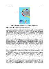
Figure 9. Average power (measured in kW/m) in the western coastlines of Sicily.
Figure 9. Average power (measured in kW/m) in the western coastlines of Sicily.
3. The Point Absorber for the Exploitation of Sea Wave Source
3. The Point Absorber for the Exploitation of Sea Wave Source
The Point Absorber here proposed is an innovative wave energy converter designed and
The Point Absorber here proposed is an innovative wave energy converter designed and
developed by the Department of Energy, Information engineering and Mathematical models (DEIM)
developed by the Department of Energy, Information engineering and Mathematical models (DEIM)
of the University of Palermo. This machine is able to directly convert wave energy into electrical
of the University of Palermo. This machine is able to directly convert wave energy into electrical
output without the use of intermediate devices [14], such as toothed wheels, transmission belts or
pressurized fluids (water or oils). Moreover, it will be able to convert wave energy independently or
output without the use of intermediate devices [14], such as toothed wheels, transmission belts
pressurized fluids (water or oils). Moreover, it will be able to convert wave energy independently
from its propagation direction. This new technology is based on an innovative small-scale prototype from
its propagation direction. This new technology is based on an innovative small-scale prototype
of a linear generator projected and realized at the DEIM laboratory. The Wave Energy Converter of a
linear generator projected and realized at the DEIM laboratory. The Wave Energy Converter (WEC) is
(WEC) is shown in Figure 10. It is fundamentally composed of two floating buoys. The external buoy
(yellow one) is the capture device, because it intercepts the continuous alternate wave motion. This
shown in Figure 10. It is fundamentally composed of two floating buoys. The external buoy (yellow
motion is transferred inside the central buoy (green in the picture), which contains the linear
one) is the capture device, because it intercepts the continuous alternate wave motion. This motion is
generators, thanks to a connecting rod (blue rod). The external buoy has a nominal diameter of 10
transferred inside the central buoy (green in the picture), which contains the linear generators, thanks
meters, while the internal one has a nominal diameter of 2 m. The working stroke of the linear
to a connecting rod (blue rod). The external buoy has a nominal diameter of 10 m, while the internal
generators is about 4 meters: so, the WEC will produce electrical energy [15] also in bad weather
one has a nominal diameter of 2 m. The working stroke of the linear generators is about 4 m: so, the
conditions (which usually represents the most energetic sea state). Additionally, most of the
WEC will produce electrical energy [15] also in bad weather conditions (which usually represents the
conversion device is under the sea level in order to avoid a significant visual impact. The presence of
most energetic sea state). Additionally, most of the conversion device is under the sea level in order to
a red light in the upper part of the WEC, at different heights in meters, makes it visible up to several
avoid a significant visual impact. The presence of a red light in the upper part of the WEC, at different
nautical miles away. Each of the eight linear generators presents a nominal power of 10 kW, for a
heights in meters, makes it visible up to several nautical miles away. Each of the eight linear generators
total nominal power of 80 kW. The particular size of the conversion device has been chosen in order
presents a nominal power of 10 kW, for a total nominal power of 80 kW. The particular size of the
to optimize the electrical energy production according to the wave climate along the western coast of
conversion device has been chosen in order to optimize the electrical energy production according
Sicily. The greater inertia of the inner buoy and the presence of a hemispherical weight in its lower
to the wave climate along the western coast of Sicily. The greater inertia of the inner buoy and the
part guarantee the correct vertical positioning of the conversion device.
presence of a hemispherical weight in its lower part guarantee the correct vertical positioning of the
Furthermore, a jumper buoy (blue one) connects the lower part of the inner buoy to the weights
conversion device.
located in the seabed, through heavy chains. The role of this jumper buoy is very important: in fact,
Furthermore, a jumper buoy (blue one) connects the lower part of the inner buoy to the weights
it is able to maintain the four lower chains in vertical position, avoiding the damage of the seabed
located in the seabed, through heavy chains. The role of this jumper buoy is very important: in
and its precious flora and fauna. Two springs are located in the upper and lower part of the inner
case, avoiding any damage of the inner buoy due to bad weather, as shown in Figure 11. Each linear of the
fact, it is able to maintain the four lower chains in vertical position, avoiding the damage
generator is composed of two parts: the stator and the translator. The first one represents the magnetic
seabed and its precious flora and fauna. Two springs are located in the upper and lower part of
the inner case, avoiding any damage of the inner buoy due to bad weather, as shown in Figure
circuit, and it is composed of two plate packs steel. The copper coils are arranged in the hollows and 11.
present a three-phase connection, that is the connection of the national grid. The second one is
Each linear generator is composed of two parts: the stator and the translator. The first one represents
composed of 132 neodymium–iron–boron permanent magnets fixed in a plate realized in a non-
the magnetic circuit, and it is composed of two plate packs steel. The copper coils are arranged in the
magnetic material, bakelite, which also has a high electrical resistance. Moreover, this particular type
hollows and present a three-phase connection, that is the connection of the national grid. The second
of magnet has been chosen thanks to its prominent features. In fact, neodymium–iron–boron magnets
one is composed of 132 neodymium–iron–boron permanent magnets fixed in a plate realized in a
are able to produce a strong and long lasting magnetic field, without any electrical energy request.
non-magnetic material, bakelite, which also has a high electrical resistance. Moreover, this particular