
Page 1 - Power_Line_Cataliotti_2012
P. 1
62 IEEE TRANSACTIONS ON POWER DELIVERY, VOL. 27, NO. 1, JANUARY 2012
Power-Line Communication in Medium-
Voltage System: Simulation Model and
Onfield Experimental Tests
Antonio Cataliotti, Member, IEEE, Dario Di Cara, Riccardo Fiorelli, and Giovanni Tinè, Member, IEEE
Abstract—The aim of this paper is to develop a complete model
of a power-line communication (PLC) system operating on a
medium-voltage (MV) network. The core-shield configuration was
chosen for signal transmission in the power cables. In order to
validate the developed model experimental, the medium-voltage
network of the Favignana island was used to carry out detailed
testing. The transmission was performed between two transformer
substations in the presence of mains voltage (i.e., 24 kV). ST7540
FSK power-line transceivers, together with capacitive coupling
interfaces, were used for the transmission and the reception of the
communication signal. The correlation between the experimental
measurements and the simulation results would appear to validate
the use of the developed model for the analysis of MV transmission
channels.
Index Terms—Communication system, medium-voltage (MV)
cable, power-line communication (PLC), power system communi-
cation.
I. INTRODUCTION
T HE application of power-line communication (PLC)
technology to the medium-voltage (MV) network of-
fers many advantages. The MV network becomes part of the
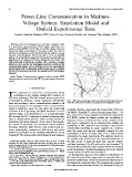
communication backbone, saving significant infrastructure Fig. 1. MV power network plan of the area of interest. In the figure, the route
costs and providing a direct communications channel to all of the MV cables can be localized, connecting the two substations 1 and 2.
connected equipment. The topology of such a communication
system is typically a mesh or a star, where the central node is limited. Therefore, in principle, the A band of the CENELEC
is located at the high-voltage (HV)/MV substation or at the
EN 50065-1 Standard [3], with a frequency range from 5 – 95
MV/low-voltage (LV) transformer [1]. In a smart automated
kHz, reserved for energy suppliers and related to narrowband
MV network, the PLC technology is oriented toward an entire
PLC (NPL), enables an adequate transfer rate. In addition, as
class of energy-related services. These services include the
diagnostic tools are developed further and the condition of the
monitoring and online diagnosis of the state of the network,
grid and its components can be estimated more reliably, the
the control of equipment, and automated instant load-flow
availability of MV power-line communication may become
recording. Moreover, other services, such as the remote me- commercially interesting for power suppliers [4]. However,
tering, power-quality measurement, fault survey, and remote
since the power grid was not originally designed for data
control for prevention of the islanding phenomenon can be
transmission, it proves in many cases to be a rather hostile
realized [2]. The amount of data interchange for these purposes
environment for signal transmission. The problems related to
the impulse noise interferences, the signal attenuation due to
Manuscript received April 27, 2010; revised June 10, 2011; accepted the high number of loads, the large scale, and the complex
September 28, 2011. Date of publication November 07, 2011; date of current
version December 23, 2011. This work was supported by STMicroelectronics. multipath topology of the MV grid are the most important. To
Paper no. TPWRD-00302-2010. overcome these problems, recent research efforts are focusing
A. Cataliotti is with the Dipartimento di Ingegneria Elettrica, Elettronica e on the investigation of signal propagation and of the channel
delle Telecomunicazioni (DIEET), Università di Palermo, Palermo 9 – 90128, characteristics of the MV networks [4]–[7].
Italy (e-mail: acataliotti@ieee.org).
D. Di Cara and G. Tinè are with the Consiglio Nazionale delle Ricerche In the literature, there are some studies on the behavior of
(CNR)-Istituto di Studi sui Sistemi Intelligenti per l’Automazione(ISSIA), MV cable lines and different approaches to model the cable are
Palermo 12 – 90141, Italy (e-mail: dicara@dieet.unipa.it; tine@pa.issia.cnr.it). proposed mainly based on the line transmission theory [8] for
R. Fiorelli is with STMicroelectronics Srl (STM), Agrate 2 – 20041, Italy
(e-mail: riccardo.fiorelli@st.com). determining the signal strength of the communication signal on
Digital Object Identifier 10.1109/TPWRD.2011.2171009 three-phase power distribution lines. The Wedepohl’s theory to
0885-8977/$26.00 © 2011 IEEE