
Page 2 - Power_Line_Cataliotti_2012
P. 2
CATALIOTTI et al.: PLC IN MV SYSTEM 63
Fig. 4. Schematization of the system under study.
Fig. 5. EVALST7540-2 reference design board [13].
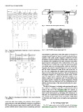
Fig. 2. Single-line wiring diagrams of substation 2. Feeder 4 connects substa-
tion 2 to substation 1.
measurements is performed in [10]. The authors in [7] and [11]
proposed a model based on Carson’s formula to calculate the pa-
rameters of the cables and the Bergeron’s method to solve the
telegrapher equation’s applied to the MV cables. Another aspect
to consider in the evaluation of the cable behavior concerns the
signal-injection configuration. Two configurations, in the case
of cable lines, are mainly used to inject the power-line signal,
core-shield, and core-core configuration. In the core-shield con-
figuration, the signal is injected between the core of one cable
and the shield connected to earth at the ends of the line. In
the core-core configuration, the signal is injected between two
phases of a three-phase power system, or between the phase and
the neutral conductor of a single-phase power system. In both
cases, the signal can be injected by capacitive couplers or in-
ductive couplers [4]. In a previous work [12], the authors have
presented a model to simulate the signal transmission through
MV cables in the core-shield and core-core configurations con-
sidering also the presence of the power transformer and a capac-
itive coupler.
The aim of this paper is to develop and experimentally verify
the model of a complete power-line communication (PLC)
system in the case of the Favignana island MV network. In
greater detail, the power-line communication channel is an MV
cable which interconnects two secondary MV substations. In
this paper, it is described first by the MV network section under
test; second, by the model of the real system implemented
Fig. 3. Single-line wiring diagrams of substation 1. Line 1 connects substation
1 to substation 2. in Simulink; and, finally, by the simulation and experimental
results.
model the cable lines enabling the prediction of the high-fre-
quency behavior of the MV distribution networks is presented in II. PLC SYSTEM UNDER TEST
[9]. Recently, a deterministic channel model for the MV under- The PLC system under test is the MV network of the Favig-
ground network transfer function based on scattering parameter nana Island in Sicily, Italy. The transmission is performed be-