
Page 3 - Power_Line_Cataliotti_2012
P. 3
64 IEEE TRANSACTIONS ON POWER DELIVERY, VOL. 27, NO. 1, JANUARY 2012
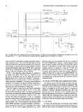
Fig. 6. Simulink model of the complete power-line communication system. All of the MV lines were modelled considering their real length and cross section
according to Fig. 2. , , , and are the transceivers terminals, where the transmitted and received voltages were evaluated.
tween two MV/LV transformer secondary substations, called 1 frequency, baud rate, and deviation) can be set by means of
and 2 as shown in Fig. 1. The route of the three-phase MV line, the EVALCOMMBOARD which is a general-purpose board
which connects the two transformer substations, can be also lo- which provides a reliable and flexible communication channel
calized in Fig. 1. The line, about 1 km long, is made up of three between a controlling PC and the EVALST7540-2 [14]. The
unipolar MV-shielded cables-type RG7H1R with an aluminum coupling interface is designed to allow the ST7540 FSK
core of 50 mm cross sections. In each substation, a power trans- transceiver to transmit and receive on the low-voltage mains
former of 160 kVA and 20/0.4 kV/kV is installed. by using a carrier frequency within the European CENELEC
In Fig. 2, the single-line wiring diagrams of substation 2 standard A-band [3]. In order to use the EVALST7540-2 for
are shown. Five switch disconnectors are installed: one for communication in the MV network, an additional interface card
the MV/LV transformer, one for the supply line, and three was designed and connected between the transceiver and the
departing lines, one of which (C01) connects to substation 1. coupling network.
Substation 2 is in an underground box. In Fig. 3, the single-line
wiring diagrams of substation 1 are shown. Three switch-dis- III. MODEL OF THE POWER-LINE COMMUNICATION SYSTEM
connectors are installed: one for the MV/LV transformer, a The complete model of the MV system for power-line com-
second one for the supply line (C02) coming from substation 2, munication was developed in the Simulink environment. The
and a third one which is available for future uses. schematic circuital representation is shown in Fig. 6. The MV
The PLC system is based on the core-shield configuration system is simulated by an MV source which is connected to
where the signal is injected between the core of one cable substation 2 through a distributed parameter line. All of the
and the shield connected to earth. The signal is injected and departing lines from substation 2 were modelled along with
received by two commercial coupling networks (CN) connected the power transformer of each MV/LV substation and the low-
to the receiving and transmitting line coupling interface of an voltage loads. The coupling network is connected to one of the
ST7540 FSK power-line transceiver. In Fig. 4, a simplified substation busbars. In the following text, the models of each part
schematic representation of the system under study is sketched. of the power-line communication system are described.
In Fig. 5, a picture of the EVALST7540-2 reference design
A. Cable Model
board is shown. The ST7540 transceiver uses frequency-shift
keying (FSK) modulation to perform half-duplex communica- As stated in the introduction, in the literature, the methods
tion on a power-line network [13]. Transmission and reception used to simulate and to study the transmission-line behavior are
sessions as well as control register parameters (e.g., carrier different. Most of them are obtained from the time-dependent