
Page 3 - 2014_A_preliminary_energy
P. 3
44 L. de Santoli et al. / Sustainable Energy Technologies and Assessments 8 (2014) 42–56
Table 2
Number of small wind systems (0–200 kW) installed in Italy per year [8].
Year 2005 2006 2007 2008 2009 2010 2011 2012
Number of wind systems 4 1 1 0 0 157 244 158
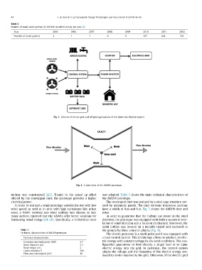
Fig. 1. Scheme of the on-grid and off-grid applications of the wind-solar hybrid system.
Fig. 2. A plan view of the AM300 prototype.
turbine was constrained) [23]. Thanks to the speed up effect was adopted. Table 3 shows the main technical characteristics of
offered by the convergent duct, the prototype provides a higher the AM300 prototype.
electrical power.
The convergent duct was realized by a steel cage structure cov-
In order to realized a wind prototype suitable for site with low ered by polymeric panels. The duct extreme transverse sections
wind speed, as well as in sites with high turbulence like urban have a width of 8 m and 6 m. Fig. 3 shows the AM300 duct and
areas, a VAWT (vertical axis wind turbine) was chosen. In fact, rotor.
many authors reported that the VAWTs offer better solutions for
harnessing wind energy [24–28]. Specifically, a H-Darrieus rotor In order to guarantee that the turbine can rotate in the wind
direction, the prototype was equipped with both a system of reve-
Table 3 3.7 lation of wind direction and a rotation mechanism. Moreover, the
Technical characteristics of AM300 prototype. 3.3 wind turbine was located on a metallic tripod and anchored to
2 the ground by three concrete plinths (Fig. 4).
Technical characteristics 360
16 The electric generator is a multi-polar and it was equipped with
Generator nominal power (kW) a load control system. This technology allows to produce an elec-
Rotor diameter (m) tric energy with constant voltage in any work conditions. This con-
Rotor height (m) figuration guarantees to feed directly a single load or to input
Carter rotation (°) electric energy into the grid. In particular, the control system
Flow area intercepted (m2) adapts the voltage and the frequency of the electric energy pro-
duced to levels required by the grid. Otherwise, if the electric grid