
Page 6 - 2014_A_preliminary_energy
P. 6
L. de Santoli et al. / Sustainable Energy Technologies and Assessments 8 (2014) 42–56 47
Fig. 7. Static and dynamic pressures profile in the average longitudinal section, with the inlet speed equal to 8 m/s.
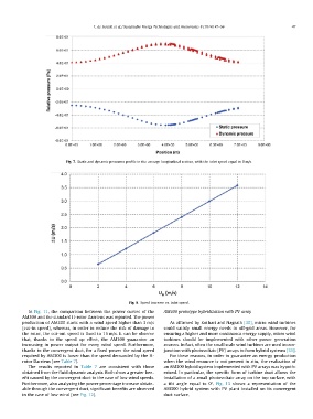
Fig. 8. Speed increase vs. inlet speed.
In Fig. 11, the comparison between the power curves of the AM300 prototype hybridization with PV array
AM300 and the standard H-rotor Darrieus was reported. The power
production of AM300 starts with a wind speed higher than 3 m/s As affirmed by Kothari and Nagrath [30], micro wind turbines
(cut-in speed), whereas, in order to reduce the risk of damage to could satisfy small energy needs in off-grid areas. However, for
the rotor, the cut-out speed is fixed to 15 m/s. It can be observe ensuring a higher and more continuous energy supply, micro wind
that, thanks to the speed up effect, the AM300 guarantee an turbines should be implemented with other power generation
increasing in power output for every wind speed. Furthermore, sources. In fact, often the small scale wind turbines are used in con-
thanks to the convergent duct, for a fixed power the wind speed junction with photovoltaic (PV) arrays to form hybrid systems [31].
required by AM300 is lower than the speed demanded by the H-
rotor Darrieus (see Table 7). For these reasons, in order to guarantee an energy production
when the wind resource is not present in situ, the realization of
The results reported in Table 7 are consistent with those an AM300 hybrid system implemented with PV arrays was hypoth-
obtained from the fluid dynamic analysis. Both show a greater ben- esized. In particular, the specific form of turbine duct allows the
efit caused by the convergent duct in the case of low wind speeds. installation of a small photovoltaic array on the top surface, with
Furthermore, also analyzing the power percentage increase obtain- a tilt angle equal to 0°. Fig. 13 shows a representation of the
able through the convergent duct, significant benefits are observed AM300 hybrid system with PV plant installed on its convergent
in the case of low wind (see Fig. 12). duct surface.