
Page 4 - 2014_A_preliminary_energy
P. 4
L. de Santoli et al. / Sustainable Energy Technologies and Assessments 8 (2014) 42–56 45
Fig. 3. AM300 duct and rotor.
Fig. 4. AM300 prototype assembled.
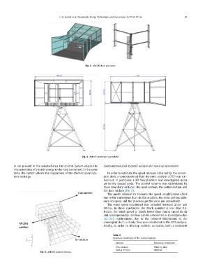
is not present in the selected area, the control system adapts the Computational fuid dynamic analysis for speed up assessment
characteristics of electric energy to the load connected. In the same
time, the system allows the regulations of the chemist accumula- In order to estimate the speed increase obtained by the conver-
tors recharge. gent duct, a computational fluid dynamic analysis (CFD) was car-
ried out. In particular, a 3D flow problem was investigated using
uniformly spaced grids. The control volume was delimitated by
three boundary surfaces: the inlet-section, the outlet-section and
the duct surface (Fig. 5).
The model allowed to evaluate the speed amplification effect
due to the convergent duct. In this analysis, the rotor motion influ-
ence on speed and the pressure profile were not considered.
The wind speed considered was included between 2 m/s and
20 m/s. In these conditions, the Mach number is less than 0.3.
Hence, the wind speed is much lower than sound speed in air
and consequentially the flow can be considered as incompressible
[22–23]. Furthermore, due to the reduced dimensions of the
convergent duct, a steady flow was considered in the CFD analysis.
Finally, in order to develop realistic scenarios, both a turbulent
Table 4
Boundary conditions of the control volume.
Fig. 5. AM300 control volume. Surface Boundary conditions
Inlet section Velocity inlet
Outlet section Outflow