
Page 8 - Reverse_osmosis2016
P. 8
190 S. Casimiro et al. / Desalination and Water Treatment 61 (2017) 183–195
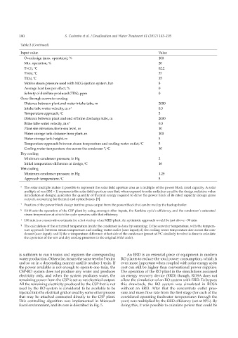
Table 3 (Continued)
Input value Value
Overdesign (max. operation), % 100
Min. operation, % 20
Tv(1), C 62.2
o
Tv(n), C 37
o
o
Tf(n), C 35
Motive steam pressure used with NCG ejection system, bar 8
Average heat loss per effect, % 0
Salinity of distillate produced (TDS), ppm 0
Once through seawater cooling
Distance between plant and water intake tube, m 2000
Intake tube water velocity, m s –1 0.3
Temperature approach, C 5
o
Distance between plant and end of brine discharge tube, m 2000
Brine tube water velocity, m s –1 0.3
Plant site elevation above sea level, m 10
Water storage tank distance from plant, m 100
Water storage tank height, m 5
Temperature approach between steam temperature and cooling water outlet, C 5
o
Cooling water temperature rise across the condenser , C 10
¶ o
Dry cooling
Minimum condenser pressure, in Hg 2
Initial temperature difference at design, C 16
o
Wet cooling
Minimum condenser pressure, in Hg 1.25
o
Approach temperature, C 5
* The solar multiple makes it possible to represent the solar field aperture area as a multiple of the power block rated capacity. A solar
multiple of one (SM = 1) represents the solar field aperture area that, when exposed to solar radiation equal to the design radiation value
(irradiation at design), generates the quantity of thermal energy required to drive the power block at its rated capacity (design gross
output), accounting for thermal and optical losses. [9].
† Fraction of the power block design turbine gross output from the power block that can be met by the backup boiler.
§ SAM sets the operation of the CSP plant by using amongst other inputs, the Rankine cycle’s efficiency, and the condenser’s saturated
steam temperature at which the cycle operates with that efficiency.
‡ 100 min is a conservative estimate for a hot startup of an MED plant. An optimistic approach would be just above ~30 min.
¶ The calculation of the saturated temperature inside the condenser is done by summing: 1) the seawater temperature, with the tempera-
ture approach between steam temperature and cooling water outlet (user input); 2) the cooling water temperature rise across the con-
denser (user input); and 3) the a temperature difference at hot side of the condenser (preset at 3 C similarly to what is done to calculate
o
the operation of the wet and dry cooling processes in the original SAM code).
is sufficient to run 6 trains and registers the corresponding An ERD is an essential piece of equipment in modern
water production. Otherwise, it runs the same test for 5 trains RO plants to reduce the total power consumption, which is
and so on in a descending manner until it reaches 1 train. If even more important when coupled with solar energy as its
the power available is not enough to operate one train, the cost can still be higher than conventional power supplies.
CSP-RO system does not produce any water and produces The operation of the RO plant in the simulations assumed
electricity only, and when the system produces water, the an energy recovery device (ERD) though, ROSA does not
remaining power from the CSP is set as net electrical output. allow the simulation of an RO system with ERD. To bypass
All the remaining electricity produced by the CSP that is not this drawback, the RO system was simulated in ROSA
used by the RO system is considered to be available to be without an ERD. After that the concentrate outlet pres-
injected into the electrical grid or used by some other process sure and mass flow rate from the first stage (for each of the
that may be attached connected directly to the CSP plant. considered operating feedwater temperatures through the
This controlling algorithm was implemented in Microsoft year) was multiplied by the ERD efficiency (set at 90%). By
Excel environment, and its core is described in Fig. 5. doing this, it was possible to calculate power that could be